01 / Design / Integration
Suspension architecture & packaging
Connecting the inboard and outboard suspension into a complete Formula SAE system, from assembly design and packaging to component stress checks.
- Team / Role
- Husker Motorsports Formula SAE
Suspension / Vehicle Dynamics Director - Project focus
- Assembly integration & component design
- Tools & methods
- SolidWorks · FEA · Suspension kinematics
01 / Context
Project overview
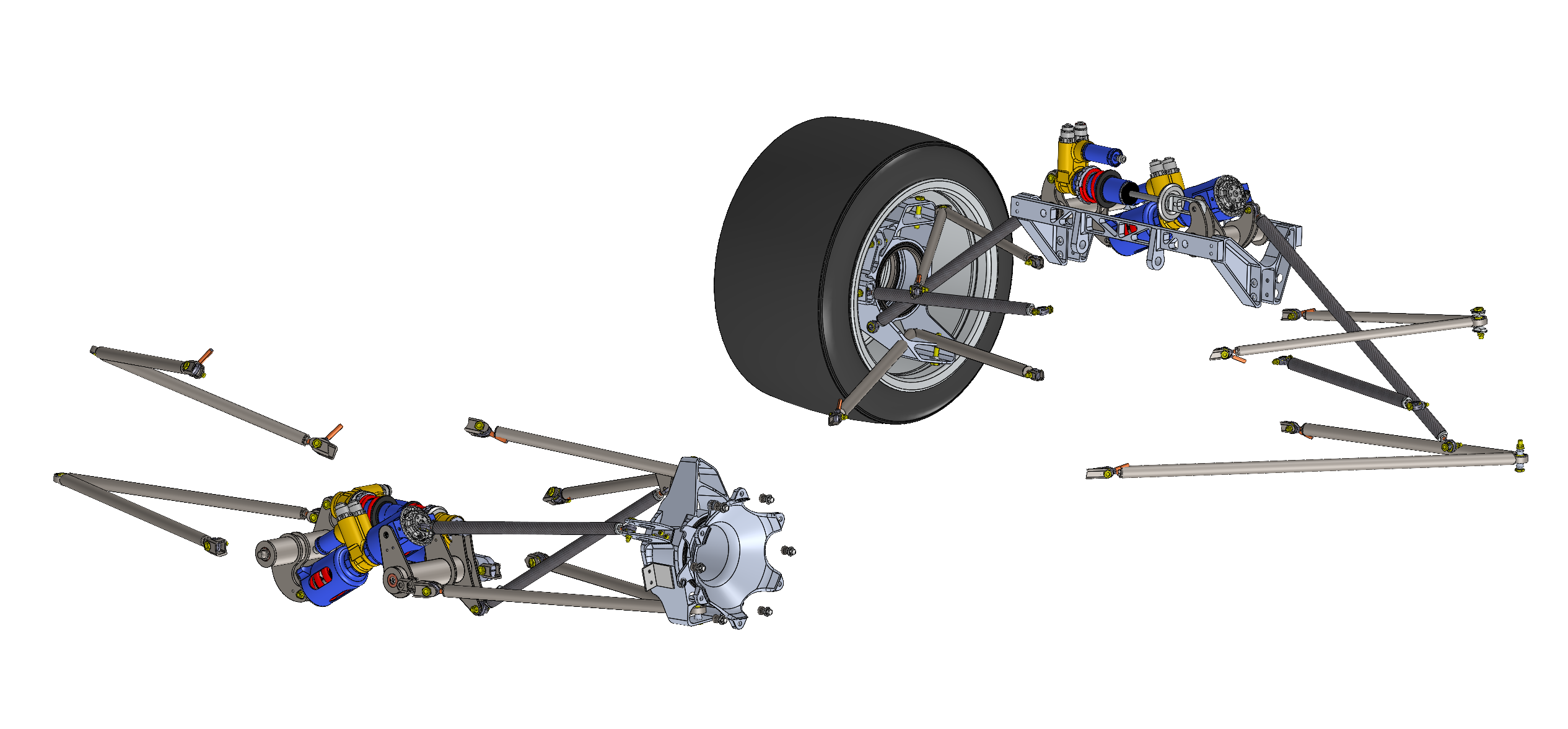
The suspension connects tire behavior to the rest of the vehicle. My work with Husker Motorsports brings the component designs together into an assembly while accounting for suspension kinematics, packaging clearances, and manufacturing.
The scope includes rockers, pushrods, control arms, uprights, hubs, and mounting components. I work across both the inboard actuation system and the outboard hardware so their interfaces can be evaluated together.
02 / The Beginning
Point Sketch
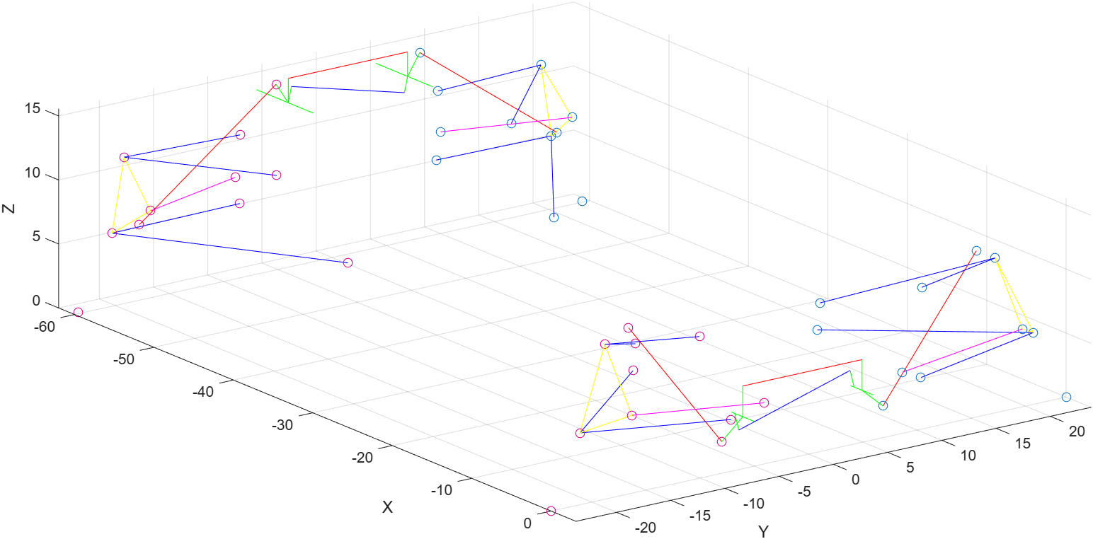
- The Point Sketch is designed as a 3D sketch in SolidWorks. It creates the placement for the car control arms, toe links, push/pull rods, and Inboard/Actuation system.
- The placement and configuration of each vehicle component are determined through vehicle dynamics analysis to optimize tire load utilization, maximize available grip, and achieve the desired kinematic and handling characteristics.
- Matlab simulations were used to validate the suspension geometry and performance, by inserting the car design into the simulation.
- Statics analysis was performed to ensure the suspension system could handle the expected loads and stresses. We also conducted dynamic analysis to evaluate the system's performance under various driving conditions.
- Matlab code was written to automate the analysis of static analysis to find the load on each suspension component. To design componets to meet the factor of saftey requirements.
03 / Inboard
The Decouple Actuation system
Connecting the Tires to the Shocks
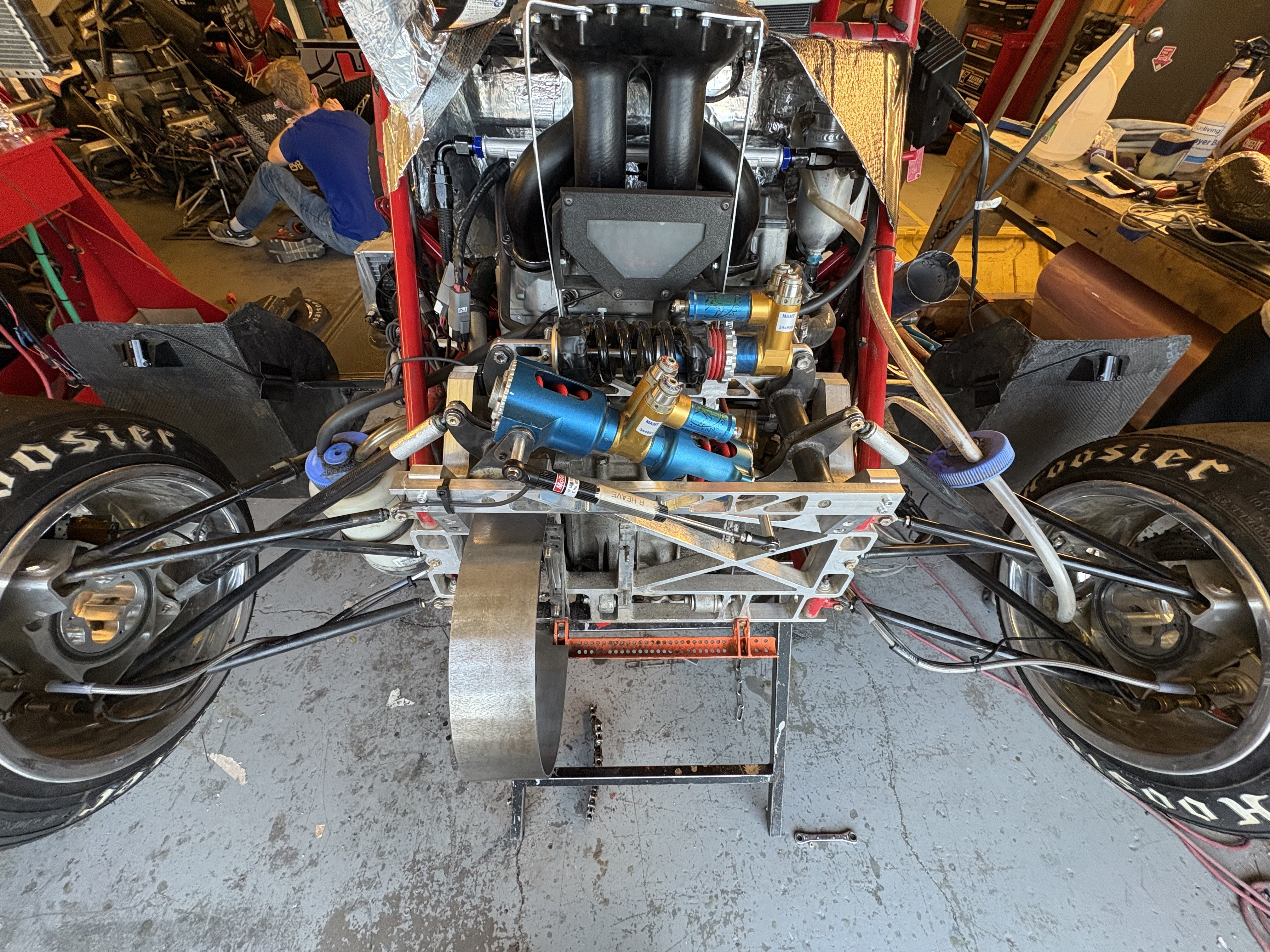
For our FSAE Team I desinged a decoupled actuation system to squeeze performance from the suspension system. Traditional suspension systems couple the heave and roll motions, compromisng spring and damper tuning. By decoupling these motions, we can optimize the spring and damper characteristics for better performance.
Check packaging and stress
Evaluate inboard packaging clearances and perform component-level FEA. Clearance checks address how parts fit together; the stress checks address component loading against the required factor of safety.
03 / Outboard
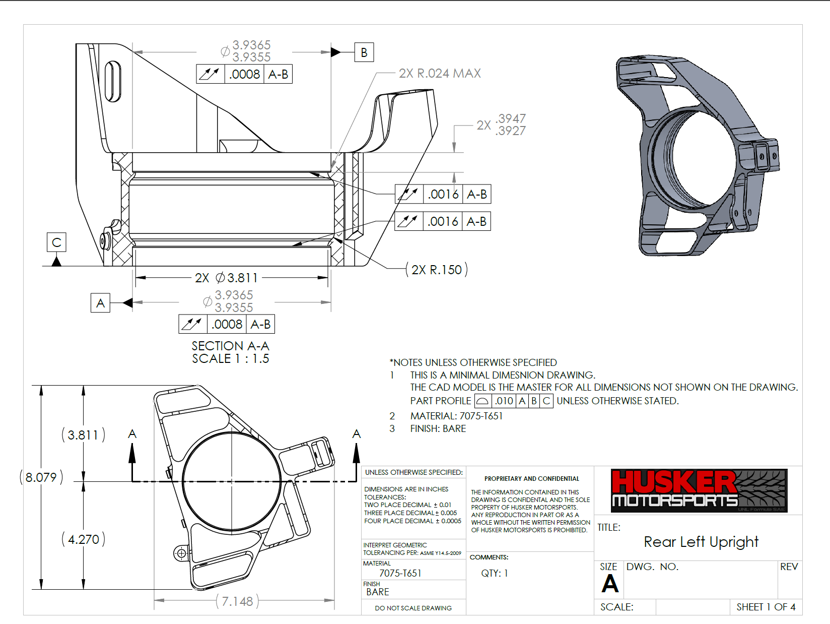
Hubs + Uprights
Connecting the Tires to the Car
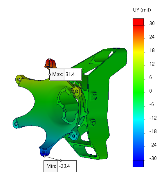
For our FSAE Team I assisted in the design and stress analysis of the hub and upright component.
Check packaging, stress, and deflection
The Hubs + Uprights connects the tires to the car, due to this deflection of the upright is study and minimized to ensure tires are at their optimal position.
04 / Gallery
More from the project
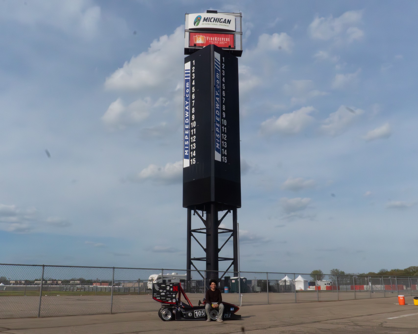
Inboard actuation close-up
Additional CAD views coming soon.